Liang Songshan, China Southern Aviation Industry Group Co., Ltd.
1. CNC Milling Process Design
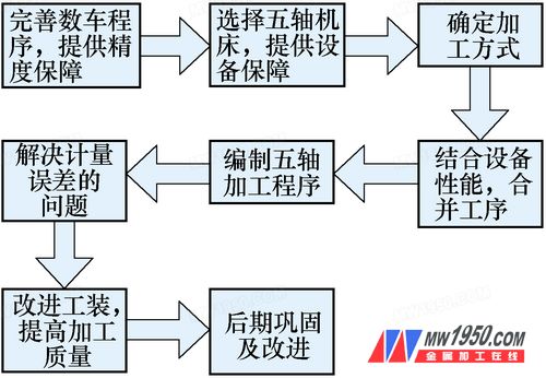
Through a comprehensive analysis of existing product specifications and the capabilities of CNC milling equipment, a new process was developed for machining the turbine grooves, as illustrated in Figure 1.
2. Technical Solution for CNC Milling
(1) Equipment Selection: Several factors impact the production schedule, primarily during the roughing and finishing stages. The capability of the roughing process limits the efficiency of the milling stage. After optimizing the turbine program, the process was shifted directly to the milling stage. However, the three sets of grooves for parts 740, 760, and 780 cannot be processed using standard CNC machines. By analyzing dimensional data and conducting process demonstrations, a specialized five-axis machining center was selected, equipped with a CNC indexing rotary table and an angle head, based on a vertical machining center. (2) Feed Method Improvement: During the 530 milling process, an elliptical shape of approximately 0.15 mm was observed, making it difficult to position the groove accurately. The flatness of the rib ring at the groove location and the spacing between ribs also showed large tolerances, affecting the positioning of G54, G55, and G66. In addition, continuous tool additions were required. Based on this analysis, the 530 process size is 44±0.2 mm, and the fifth-stage groove direction ranges from f558 to f623 mm, which creates a large section causing significant stress accumulation. Stress release during subsequent steps leads to poor flatness on the bearing surface, affecting the accuracy of the groove ribs and the relative plane of the ring. The number of empty cuts in this step is excessive, resulting in wasted resources and increased labor hours. The proposed solution includes replacing the 80° external circular cutter with a straight insertion tool and using a 6 mm wide groove cutter with R0.8 mm instead of an R3 mm round groove cutter (see Figure 2).

Figure 2

Figure 4 Turbine Groove Profile
Guide Ring is a mechanical seal, also known as a guide ring. It is usually made of metal or plastic and used to support and position pistons or rods. Guide Ring has excellent wear resistance and corrosion resistance, which can effectively reduce leakage and friction, thereby extending equipment life. Guide Ring is widely used in the hydraulic, pneumatic, mechanical, and automotive industries as an important mechanical seal.
The classification of Guide Ring can be divided by material, structure, and purpose. According to material classification, Guide Rings are mainly divided into metal Guide Rings and plastic Guide Rings. Metal Guide Rings are usually made of metals such as copper, iron, and stainless steel, which have high strength, wear resistance, and high-temperature resistance; The plastic Guide Ring is usually made of polytetrafluoroethylene (PTFE), nylon, polyimide and other materials, with good corrosion resistance and low friction coefficient.
According to structural classification, Guide Rings are mainly divided into unidirectional Guide Rings and bidirectional Guide Rings. A unidirectional guide ring can only withstand pressure in one direction and is typically used in hydraulic and pneumatic systems; The bidirectional guide ring can withstand bidirectional pressure and is typically used in the mechanical and automotive industries.
According to usage classification, Guide Rings are mainly divided into piston Guide Rings and rod Guide Rings. The piston guide ring is usually used to support and position the piston, preventing friction and leakage between the piston and the cylinder liner; The rod guide ring is used to support and position the rod, preventing friction and leakage between the rod and the seal.
Wearing,Guide Ring,Guide Strip
DG Zhongxingshun Sealing Products Factory , https://www.zxs-seal.com