China Southern Aviation Industry Group Co., Ltd. Liang Songshan
1. CNC Milling Process Design
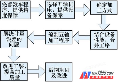
Through a comprehensive analysis of existing product quality and the capabilities of CNC milling equipment, a new CNC milling process for turbine grooves was designed, as shown in Figure 1.
2. Technical Solution for CNC Milling
(1) **Equipment Selection Analysis** The main factors affecting the production schedule are the rough machining and milling stages. The capability of the rough machining stage also limits the milling process. To optimize and improve the turbine program, a direct transition to the milling process was implemented. However, certain parts (models 740, 760, and 780) could not be processed by standard CNC machines. Based on dimension data acquisition and process simulation, a non-standard five-axis machining center was selected, equipped with a numerical control indexing turntable and an angle head, based on a vertical machining center. (2) **Feed Method Improvement** During the 530 milling process, the machine produced an elliptical shape of about 0.15 mm, making positioning difficult and affecting the accuracy of the groove milling. Additionally, the flatness of the rib ring and the spacing between ribs were inconsistent, causing issues with G54, G55, and G66 positioning. Continuous tool additions were required during the process. To address this, the 80° external circular cutter was replaced with a straight insert, and a 6 mm wide, R0.8 mm groove cutter was used instead of a R3 mm round groove cutter (see Figure 2).

Figure 2

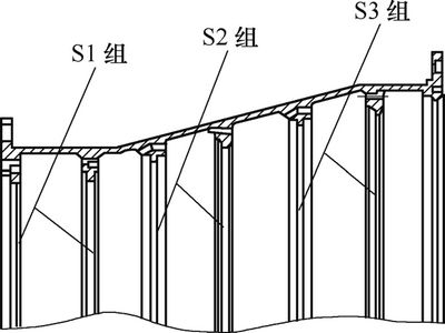
Figure 4 Turbine Groove Profile
Wiper Seals are a type of mechanical seal commonly used to protect piston rods and pistons in hydraulic and pneumatic equipment. The main function of Wiper Seals is to prevent dust, dirt, and other impurities from entering the interior of the equipment, thereby protecting the sealing performance of the piston rod and piston, and extending the service life of the equipment.
Wiper Seals are typically made of elastic materials such as polyurethane, nitrile rubber, fluororubber, etc. These materials have excellent wear resistance and chemical resistance, and can maintain stable performance in various harsh environments.
Wiper Seals are typically divided into two types: unidirectional and bidirectional. Unidirectional Wiper Seals can only prevent dirt and impurities from entering the device from one direction, while bidirectional Wiper Seals can simultaneously prevent dirt and impurities from entering the device from both directions.
Wiper Seals can also be customized according to different application requirements. For example, for high-speed rotating devices, special Wiper Seals can be used to ensure that they do not generate excessive heat and friction during high-speed rotation. For equipment used in harsh environments, special materials such as corrosion-resistant, high-temperature resistant, and low-temperature resistant Wiper Seals can be used.
In summary, Wiper Seals are in dispensable mechanical seals in hydraulic and pneumatic equipment, and their excellent performance and reliable sealing performance provide important guarantees for the normal operation of the equipment. If you need a Wiper Seals product, you can contact a professional seal manufacturer to customize the appropriate Wiper Seals for your device according to your specific needs.
Wiper Ring,Hydraulic Wiper Seal,Double Lipped Wipers,Dust Seals
DG Zhongxingshun Sealing Products Factory , https://www.zxs-seal.com