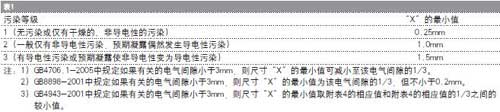
Safety distance analysis:
Whether it is a metal screw as a protective ground connection in a Class I device or a mechanically fixed metal screw in a Class II device, whether it is accessible or only as an intermediate unconnected conductor, unless between the screw and the hazardous live parts Even if the short circuit does not affect the electrical safety, otherwise a certain safety distance must be met between the metal screw and the dangerous live parts. Because the screw itself does not have a penetration distance, the so-called safety distance here refers to the clearance and creepage. distance. Clearance refers to the shortest spatial distance measured between two conductive parts or conductive parts and equipment interface. The influence factors are mainly pollution level, overvoltage category and peak operating voltage. Creepage distance refers to two measured along the insulation surface. The shortest distance between conductive parts or between the conductive parts and the protective interface of the equipment. The influence factors are mainly pollution level, material group and effective or DC working voltage.
The higher the level of the influence factor, the larger the minimum clearance and creepage distance required. For example, the switching power supply circuit widely used in electronic products, engineers can use different topologies to achieve the same function output, but different topologies. The corresponding working voltage between the primary and secondary is different, and the higher the operating voltage, the greater the required safety distance. GB/T 16935.1-1997 "Insulation coordination of equipment in low-voltage systems Part 1: Principles, requirements and tests" describes in detail the principle of insulation coordination, the rules for determining the insulation distance dimensions and related test measurement methods, and different electronic product standards, For example, GB 4706.1-2005, GB 8898-2001 and GB4943-2001 also specify specific requirements for the relevant product characteristics according to this standard, and will not be repeated in this paper.
It should be emphasized here that in practical applications, the structure of various electronic products is ever-changing, and the electrical insulation composition is also diverse. Sometimes there are grooves, partitions or gaps. We are confirming metal screws and other The following rules apply to the safe distance between related components:
(1) The minimum creepage distance should not be less than the minimum clearance in any case.
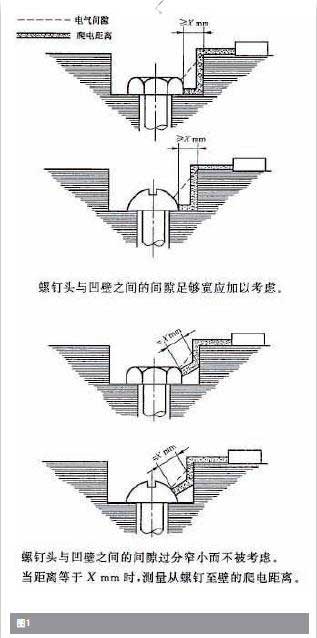
(2) If the path under consideration includes a groove of any depth and a width of less than X mm or a converging edge, both the clearance and the creepage distance are measured directly across the slot.
(3) If the path under consideration includes a groove of any parallel depth with a width equal to or greater than X mm, the clearance is the line-of-sight distance between the two, and the creepage distance is measured along the contour of the groove.
(4) If the path considered includes a V with an internal angle less than 80° and a width greater than X mm
The slot, then the clearance is the line of sight distance between the two, and the creepage distance is measured along the contour of the slot, but the bottom of the slot is bridged by a length of X mm.
(5) If the path considered includes a rib, the clearance is the shortest straight space distance through the rib top, and the creepage distance is measured along the contour of the rib.
(6) If the path under consideration includes an unbonded joint and the joint is at a distance from the components on both sides, the clearance and creepage distance shall be measured through the gap and shall be carried out in accordance with Clauses 2 and 3.
(7) If the metal screw itself is an unconnected conductive part on the path considered, the size of this screw is considered to be zero for clearance and creepage distance.
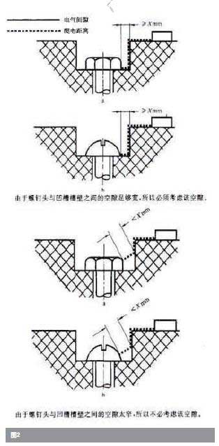
(8) If the metal screw is in the groove and there is a certain gap between the groove and the groove wall, the determination of the clearance and the creepage distance is complicated. Since there is no relevant path diagram in GB 4706.1-2005, we refer to the diagram in GB/T 16935.1-1997 (Figure 1), and then related diagrams in GB 8898-2001 and GB 4943-2001 ( Figure 2) For comparison, you will find the gap between the screw head and the groove wall.
As for the size specification of "X mm" mentioned in the above rules, see the following table:
In the process of electronic product development, the rationality of structural design plays a significant role in the overall electrical safety and electromagnetic compatibility performance. From a safety point of view, the electrical and mechanical connections between the various components inside the electronic product must have sufficient mechanical strength and reliability. In most cases, metal screws are commonly used as fasteners. Screws can be divided into various types, such as head type, groove type and thread type. Engineers can choose to fix and print the outer casing and bracket according to actual needs. For fixing of the plate, fixing of the heat sink, and fixing of various types of terminals, screws made of materials such as zinc or aluminum or easily deformable are not suitable for this. For screws that simultaneously perform electrical and mechanical fixing functions, not only strong contact is required. To avoid excessive contact resistance caused by poor contact, resulting in overheating and causing insulation damage to the product. It is also required that under the condition of withstanding external force under the condition of foreseeable external force, the safety distance may be reduced and the electric shock risk may be caused.
  Mechanical specification
Regardless of the single screw used in the electronic product for electrical connection or / and mechanical fixing, in GB 4706.1-2005 "Safety of Household and Similar Electrical Appliances Part 1: General Requirements" and GB 8898-2001 "Audio, Video and This type of screw test is specified in the Safety Requirements for Electronic Equipment. Screws that are screwed into the insulating material are tightened and loosened 10 times each time, and should be completely unscrewed and screwed in each time; other screws are tightened and loosened. 5 times, there should be no damage after the test that affects the use of this fastening device or electrical connection, in other words, electrical safety degradation cannot occur.
In addition, GB 4943-2001 "Safety of Information Technology Equipment" does not require torque testing of screws, but in the terms of wiring and terminal connections, the application of screws is also required, such as not being able to fully contact the clamping current. Wide-pitch screws with components not equipped with locking devices and self-tapping screws that do not tap the full standard mechanism threads shall not be used for electrical connections; if electrical contact pressure is required, the screws engage with metal plates, metal nuts or metal inserts At least two full threads shall be provided; unless the metal parts have sufficient elasticity to compensate for any shrinkage or deformation that may occur in the insulation, the electrical connection shall not transmit contact pressure through the insulating material; the terminals shall be designed so that the screws holding the wires are tightened When the wire does not slip off, the screw that clamps the external power lead should have a thread according to ISO 261 or ISO 262 or a thread with a pitch and mechanical strength equivalent; for the AC grid power conductor and the protective ground conductor terminal, Dimensions must comply with the regulations.
hose clamp,clamps hose,v band hose clamps
Aojin Hose Clamp Factory , http://www.tjhoseclamp.com